Subsection 4.4.3 AC Generators
A synchronous generator is a device that converts mechanical energy into electrical energy by utilizing the principle of electromagnetic induction.
According to Faraday’s law of electromagnetic induction, a moving or changing magnetic field induces an electric voltage in a nearby conductor. If the conductor forms a closed loop, an electric current will flow and electrical power will be transmitted.
An electrical generator consists of two main mechanical components: a rotating part called the rotor and a stationary part called the stator, and two main electrical components: the armature and the field.
Both the armature and the field are made of a conducting material, usually copper wire, wound into multi-loop coils called windings. The rotor is connected to a prime mover, such as a steam turbine or a diesel engine which supplies the mechanical energy to the generator.
The field windings are like an electromagnet. When direct current (DC) flows through the field windings, a magnetic field is created similar to the one which surrounds the north and south poles of an ordinary magnet, but adjustable. The strength of the field is controlled by the amount of the field current. The process of supplying electrical current to the field winding is known as excitation.
The armature windings are the part of the generator where the voltage is induced. The armature consists of several individual windings connected in a specific configuration. The end points of the armature windings are called the generator terminals. As long as the generator is spinning, the field will induce a sinusoidal AC voltage into the armature windings. The armature windings deliver power to the terminals and thence to the load circuit.
In a typical AC synchronous generator, the rotor carries the field windings and the stator carries the armature windings, however the opposite arrangement is also possible.
Single-phase generator.
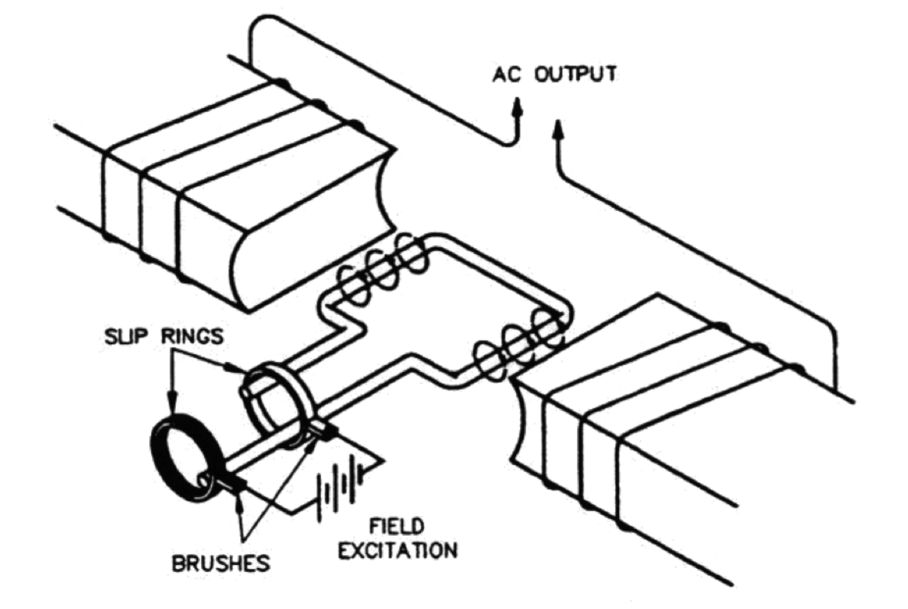
The diagram below shows a simplified AC, single-phase synchronous generator, illustrating the rotor, stator, armature and field.
A prime mover such as an engine or turbine spins the rotor and supplies the input mechanical energy. The rotor carries an externally energized electromagnet (the field) which creates a magnetic field. The rotor is surrounded by the stator, which carries multiple turns of copper windings, (the stationary armature). The ends of the armature windings are the generator terminals; the external circuit begins and ends there.

As the rotating magnetic field passes by the stationary armature, a voltage is induced in the armature. This voltage varies in magnitude and direction sinusoidally, as shown in Figure 4.1.5.
The frequency is related to the rotor rpm according to this relation:
\begin{equation*}
f = \frac{120 \times N}{2 \times 60}
\end{equation*}
where f is the frequency in Hz and N is the total number of poles.
For a two-pole field (one north and one south pole) rotating at 3600 rpm, the voltage will alternate through 60 cycles each second i.e. 360 Hz. With a four-pole field, the north and south poles will pass by the armature windings twice per rotation. As a result, a four-pole generator will produce the same frequency as a two-pole generator while spinning at half the speed.
Although the voltage continuously varies from instant to instant, we represent the sine wave voltage using its RMS average.The RMS voltage is proportional to the speed of rotation and also the strength of the magnetic field, therefore the generator output voltage can be adjusted by controlling the current that creates the field.
Three-phase generator.
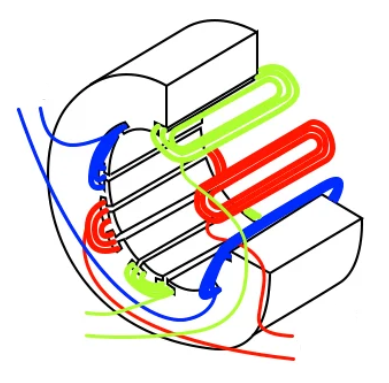
To generate three-phase power, the stator is fitted with three armature windings arranged symmetrically, 120 degrees apart from each other. The three windings are connected together with the common point designated neutral.

As the rotor rotates, the rotating magnetic field induces voltages into each stator winding in turn, generating three sine waves of voltage, equally spaced, shown below.


