Subsubsection Flanged Connections
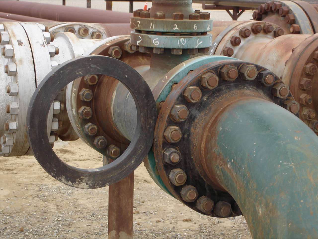
Flanges are circular discs with machined faces, attached to the ends of a section of pipe. Flanges provide a method of connecting pipes, valves, pumps and other equipment to form a piping system.
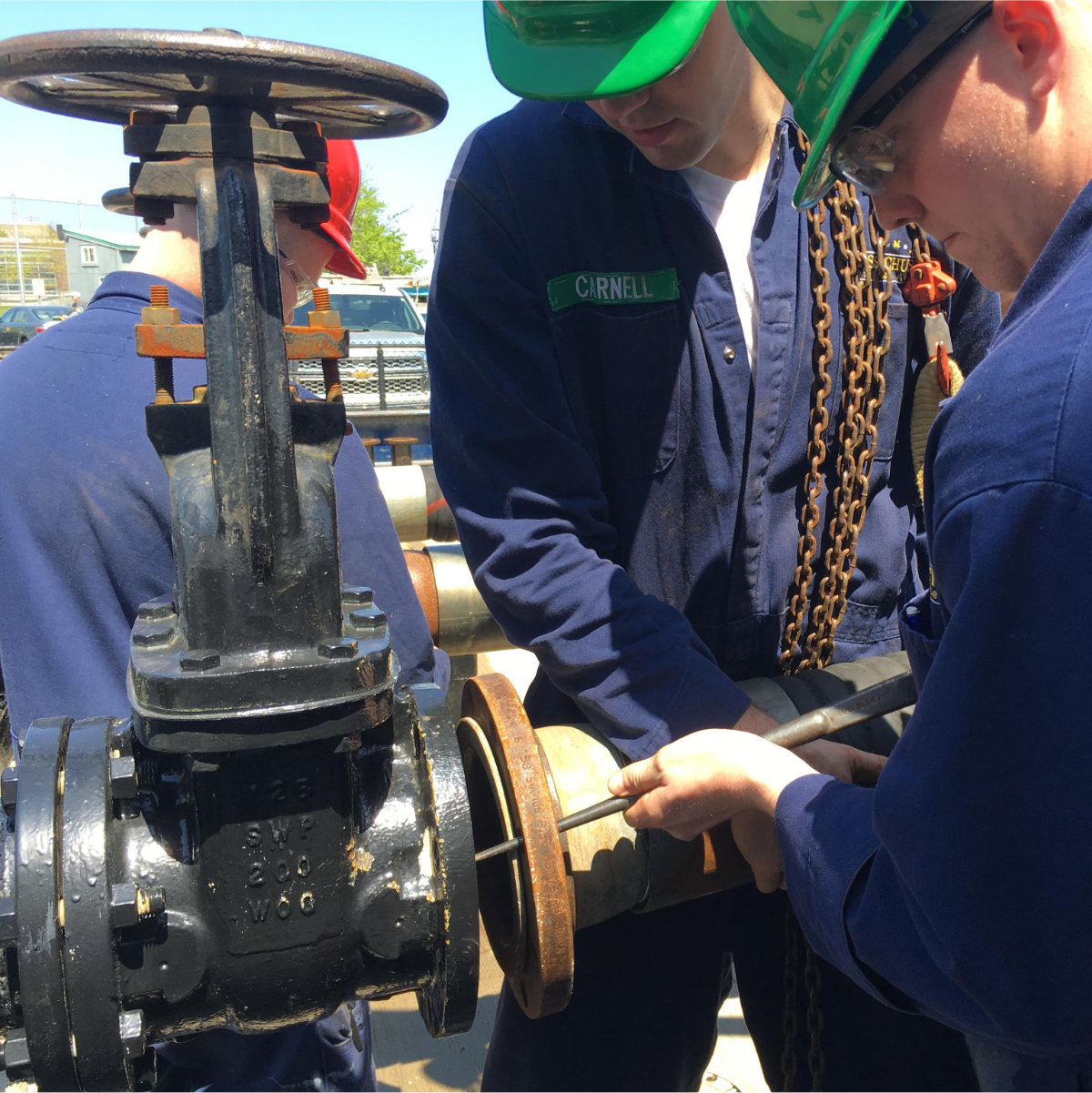
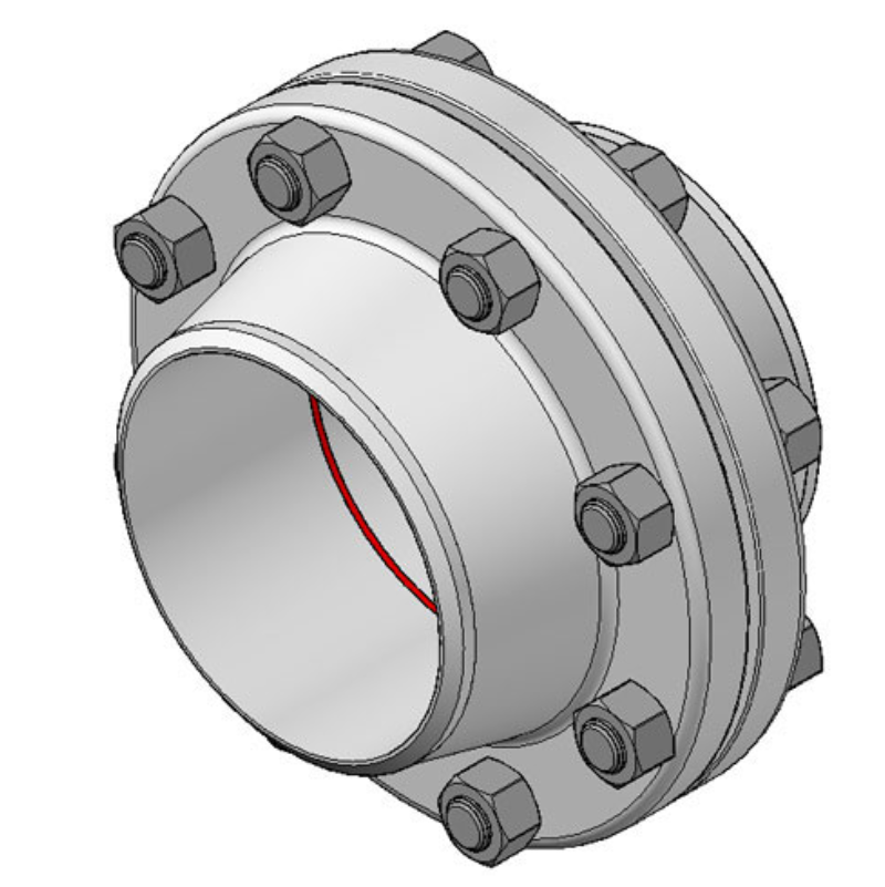
Flanged joints are made by bolting together two adjacent flanges with a gasket between them to provide a seal. Flanged connections are used for higher-pressure applications and situations where dismantling might be necessary.
The materials and design of the flanges are governed by the requirements of service, and in most cases, a flange is of the same material as the pipe. Flanges in steel piping systems are usually screwed or welded to the pipe or tubing, while flanges in nonferrous systems are usually brazed.
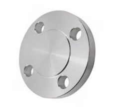
A blind flange (also called a ’closure plate flange’) has no center hole, so nothing can flow through the flange. Blind flanges may be used to temporarily seal a piping system while testing, modifying or repairing the line, to create an access point in a piping system, or to create a long-term seal to terminate a piping system that is not used.
A spectacle blind flange is shaped like a pair of glasses or spectacles— hence the name. One half is open to allow flow through during normal operation and the other side is solid to block flow and secure the system for maintenance. The two halves are separated by a spacer with a hole for one flange bolt. They are generally installed in the piping system permanently.
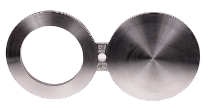
To change the position, the system must first be secured, depressurized and locked out. After removing the flange bolts, the spectacle blind can be rotated to the other side, the gaskets replaced, and the bolts retightened.
An orifice flange is used in conjunction with a differential pressure sensor to measure the rate of flow in the pipe.
An orifice is a hole through which fluid may pass. When fluid flows through an orifice it creates a pressure drop, which is measured by the pressure sensor. The flow rate through the orifice is proportional to the square root of the pressure drop and can be calculated knowing the orifice diameter.
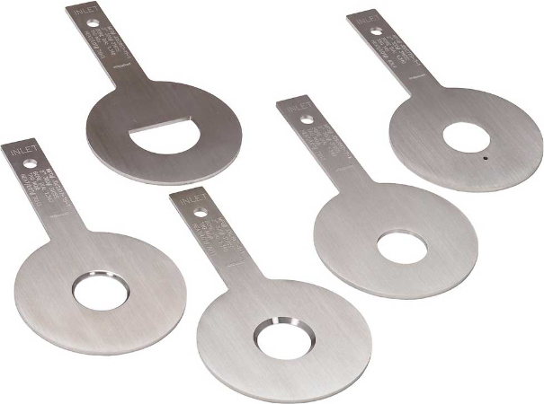
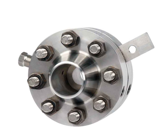
The orifice flange assembly consists of a pair of flanges containing pressure taps, an orifice plate, jacking screws and the normal gaskets, nuts and bolts. The orifice plate has a precision hole (the orifice) drilled through its center, and a tab stamped with the hole diameter. Taps are threaded holes drilled through the flanges where the differential pressure sensor is connected. The jacking screws are used to spread the flanges when replacing the orifice plate.
