Subsubsection Bourdon Tube Gauges
Pressure Gauge Construction.
A Bourdon tube pressure gauge is a mechanical device used for measuring pressure.
The key element is the Bourdon tube, a C-shaped tube typically made of metal such as brass, bronze, or stainless steel. A Bourdon tube gauge relies on the elasticity and mechanical properties of the Bourdon tube to sense pressure. When pressure is applied, the tube straightens or uncoils slightly. This deformation is transmitted through a linkage and gear to a pointer, which moves across the calibrated dial to indicate the pressure.
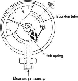
Bourdon tube gauges are simple, robust, and they require no external power. They are durable, capable of withstanding harsh environments and high pressures, and provide reasonably accurate readings for many industrial applications. However, there are some limitations. Bourdon tube gauges can be sensitive to extreme temperatures, which may affect their accuracy. Over time, the moving parts may wear out, necessitating maintenance or replacement. Additionally, they are not suitable for very low or very high-pressure measurements beyond their design specifications.
All bourdon tube gauges measure gage pressure, that the indicator points to zero when they are connected to atmospheric pressure. All other measurements are relative to this zero value.
Several types of Bourdon tube gauges are available for different applications. Scales marked using various units are also available.
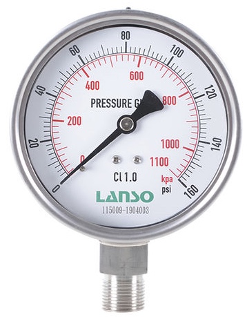
Simplex Gauge: This is a basic bourdon tube gauge, designed to measure positive pressures only. The scale starts at atmospheric pressure on the left and rotates clockwise as the measured pressure increases. A peg on the face prevents the pointer from moving below 0. The gauge is a dual-scale model, with pressure indicated in both psig and kPa.
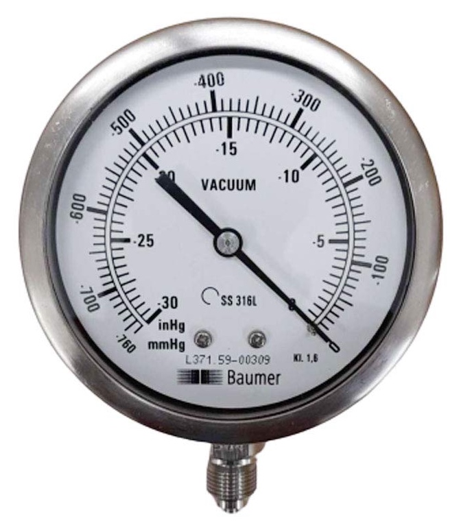
Vacuum gauge:Vacuum gages are designed to measure pressures below atmospheric only. The scale starts at zero on the right and rotates counterclockwise as the absolute pressure decreases and the vacuum increases. The maximum values on the gauge corresponds to the maximum possible vacuum that can be achieved relative to the atmospheric pressure, approximately 30 inches or 760 mm of mercury vacuum. Note that the gauge below has dual scales: inches of mercury vacuum and mm mercury absolute.
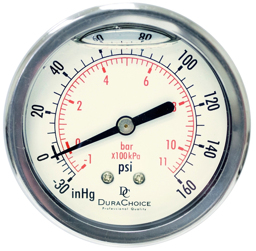
Compound Gauge: These gauges can measure both positive and negative (vacuum) pressures, making them suitable for applications where both types of pressure need to be monitored. There is no distinct zero point on these gauges because it moves as the atmospheric pressure changes. The pressure and vacuum scales are usually marked with different units. On the gauge shown, positive pressures are in psi or bar, and vacuums are in inches mercury, and bars absolute.
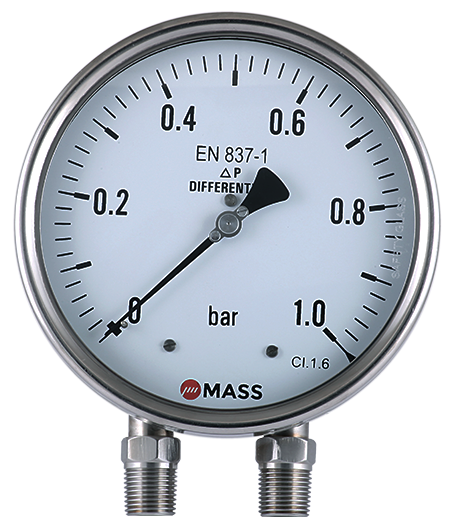
Differential Gauge: This gauge is designed to measure the pressure difference between points. Internally, there are two bourdon tubes, and the linkage is arranged to move the pointer based on the difference between them. These gauges are recognizable because they have two pressure connections, but only one pointer. Differential gauges are often used to measure the pressure drop across filters or strainers. An increasing pressure drop is an indication that the strainer needs to be cleaned or the filter changed.
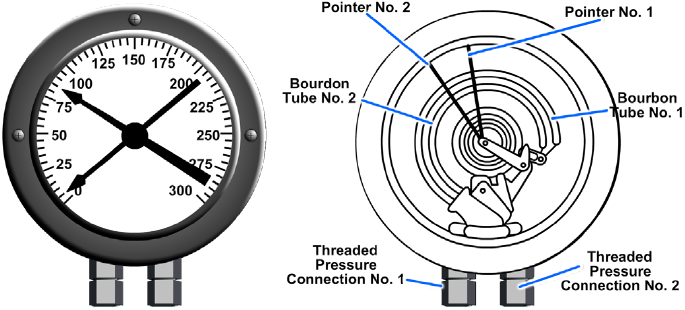
Duplex Gauge: This type features two separate bourdon tubes and pointers within a single gauge housing, allowing simultaneous measurement of two different pressures. Useful for displaying two different but related pressures simultaneously, for example the inlet and outlet pressures on a heat exchanger.
Gage calibration involves comparing a gauge’s readings against a known standard or reference to ensure accuracy and correct any discrepancies. Gages are initially calibrated at the factory, but they should also be recalibrated at regular intervals. Recalibration helps to detect and correct drift, wear, or damage in the gauge, thus ensuring reliable performance. The frequency of recalibration depends on factors such as the gauge’s usage, the criticality of the measurements, and manufacturer recommendations.
Two adjustments are usually made when performing a calibration.
Zero Adjustment: This is typically done first. The gauge is checked at no pressure, and adjustments are made to set the pointer at zero. This ensures that the gauge has no offset error.
Span Adjustment: After setting the zero point, the gauge is subjected to its maximum rated pressure to check the upper end of the scale. Adjustments are then made to ensure that the gauge reads accurately at this high-pressure point. This process might also include intermediate points to verify linearity across the span.

