Subsection 8.2.1 Description
As discussed in Subsection 4.4.3, the essential components of an AC generator are the armature and the field, one of which is located on the rotor and the other on the stator. However a practical generator requires many other components, including an enclosure, bearings, cooling, lubrication, instrumentation and control, and a method to excite the field.
These components are shown in Figure 8.2.2 and Figure 8.2.3 and discussed below.
The shaft is supported by two journal bearings (7 and 13), one on the drive end (DE) and the other on the non-drive end (NDE). Each bearing has its own integral oil sump with sight glass, cooling fins, and an oil ring that circulates the oil to the top of the shaft as it rotates.
The shaft itself supports and carries the rotating components: primarily the main rotor core (9) and the 8-pole main field windings (4), but also a cooling fan (2) and several other components (10, 11, 12, 14, 16, and 19) that are required to excite the generator. Excitation systems will be discussed in Subsection 8.2.2.
The main field (4) on the rotor is wound to create eight alternating north and south poles. The main stator core (8) surrounds the main rotor (9) and is wound with three main armature windings (3). As the shaft rotates, the rotor’s magnetic field sweeps by the each of the three armature windings in turn, and induces a sinusoidal voltage in each as shown in Figure 4.4.7. The resulting 3-phase AC is directed to the generator terminals (23), and from there connections are made to the main switchboard.

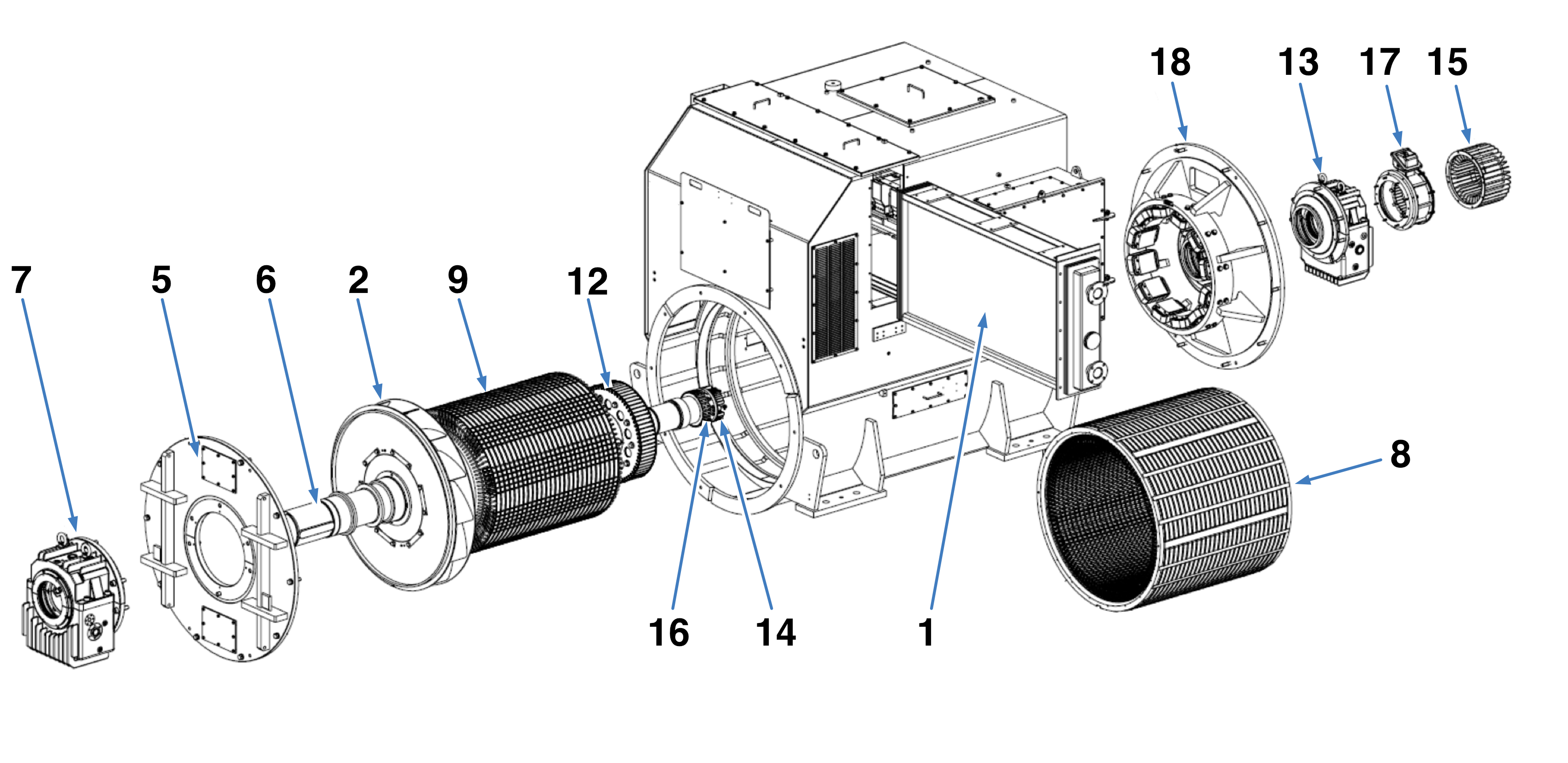
- Water cooled Air Cooler
- Ventilation Fan
- Main Armature Winding
- Main Field Windings
- End Shield (DE)
- Shaft
- Bearing (DE)
- Main Stator Core
- Main Rotor Core
- Main Field Terminals
- Leads to/from Rectifier
- Exciter Rotor Core
- Bearing (NDE)
- Rotating Rectifier
- Rectifier Cover
- Permanent Magnet Rotor
- Permanent Magnet Stator
- End Shield (NDE)
- Exciter Armature Winding
- Exciter Field Winding
- Exciter Stator Core
- Current Transformer
- Main Terminal Box
Both the main core and the stator core are made of thin sheets of electrical steel, called laminations, clamped tightly together. The stationary armature windings (3) and the rotating field windings (4) are inserted into slots formed when the laminations were pressed out, and are firmly wedged in to hold them in position.
Electrical steel is a speciality steel used in the cores of electrical machines such as motors, generators, and transformers. It is an iron alloy with silicon (instead of carbon) as the main additive element. Silicon increases the electrical resistivity of iron by a factor of about 5. Electrical steel also has favorable magnetic properties which tend to reduce magnetic hysteresis— an energy loss caused by the repeated magnetization and de magnetization of the core. These properties reduce energy losses in the core by about three times compared to conventional steel,
The laminations are insulated from each other to prevent current from flowing axially along the core. These currents, called eddy currents, are another source of energy loss, so using insulated laminations improves the generator efficiency.
Generators produce lots of heat while they are operating due to unavoidable losses caused by mechanical friction and electrical resistance, and other factors. If this heat is not removed as it is produced, the generator temperature will rise to unacceptable limits, and high temperature is extremely damaging to electrical insulation. Electrical machines are designed to run for 100,000 hours or more when operated at or below their design temperature limit, however for every 10° C rise above this temperature, the thermal life expectancy of the electrical insulation is reduced by half, so generator cooling is critical.
The generator’s cooling system uses the shaft driven internal fan (2) to circulate the air through the machine. This hot air passes over a water-cooled heat exchanger where it is cooled and then recirculated. The cooling water tubes are double walled with slotted plate fins. Water flows through the inner tube and cools the outer tube and the slotted fins. Air flows between the fins and around the outer tubes and so is cooled.
In the case of a tube leak, water will flow between the inner and outer tubes to a leak detector and trigger an alarm. This prevents water from leaking on to the electrical components.
If for some reason the cooling water is not available, an emergency cooling mode is available. In this mode cover plates on the generator are removed to allow the fan to draw cool air from the engine room and discharge the heated air outside the generator.
